There's an old gambling expression that goes "Let it ride." This denotes letting all your winnings ride on the next bet. That expression pretty much sums up the theme for this episode.
It's been a while since I wrote Episodes #8, and #13, on building my 1921 Harley-Davidson replica racer. These two technical episodes get more page views than any of my history episodes.
While I have done a couple of updates on these earlier episodes, I've decided to start a new continuing episode on upgrading my racer.
Like most of my projects, this one begins with the delivery of a box. One day my wife told me I had a large box from Europe sitting in the garage. I'd been waiting for it for a couple months and was excited to see if it would work. Once I got the box down to my shop, and unwrapped, my earlier suspicions about the amount of work this conversion would take where confirmed.
The Mystery Box
For the most part, early Harley-Davidson racers, came without clutches, transmissions, or functioning brakes. That makes them nearly impossible to ride, except on the racetrack. I decided to Convert my racer so it can be ridden at antique motorcycle events, which will require a working clutch, and brake.
In 1912, Harley-Davidson introduced a single speed clutch built into the rear wheel hub. Known as a "Free Wheel Clutch", it allowed riders the ability to have the engine running, while the bike was stationary. This clutch setup was also an option for the factory produced racers.
Harley-Davidson Free-wheel Control Ad Motorcycle Illustrated - 1912
Replica Freewheel Clutch
When I compared the clutch setup I received, to the space between my frame's rear axle plates, I realized it would not even close to fitting my frame. I had been assured it would bolt on, but there was no way if would fit, as it was too wide. Fitting it to my frame would require removing the right-side drum brake, and re-machining the rear hub width to narrow it. Guess I should have listened to that little voice, told me not to go down this path.
I checked the function of the clutch assembly, and it worked fine. Several folks familiar with the overseas supplier, had warned me it would be a waste of time, to try and return it for a refund. That meant that I would have to do whatever was necessary to get this clutch to work on my frame.
My weapon of choice in taking on this task, was my leather belt drive vintage South Bend metal lathe. I think my wife's grandfather bought this lathe for the family lumber mill sometime in the thirties or forties. A few years ago, I became the caretaker of this family mechanical heirloom.
My Belt Drive South Bend Metal Lathe
I've never claimed to be a trained machinist, so this project really tested my machining skills. Most of what I learned about operating a metal lathe, came from watching my grandfather, who was a master metal worker all his life. After countless hours of measuring, and lathe work, I was able to fit it in the space available, and the clutch worked properly.
Clutch fit to my Keystone Frame
When my machine work was complete, and the clutch was fitted, it was apparent that the center line of the new rear hub, would not line up with the frames center line. This was caused by the worm gear clutch activator on the left side of the hub. The width of this mechanism could only be narrowed slightly, and still function. I would not be able to determine just how much the rear wheel was of center until the rear wheel had a rim laced to it, and tire mounted.
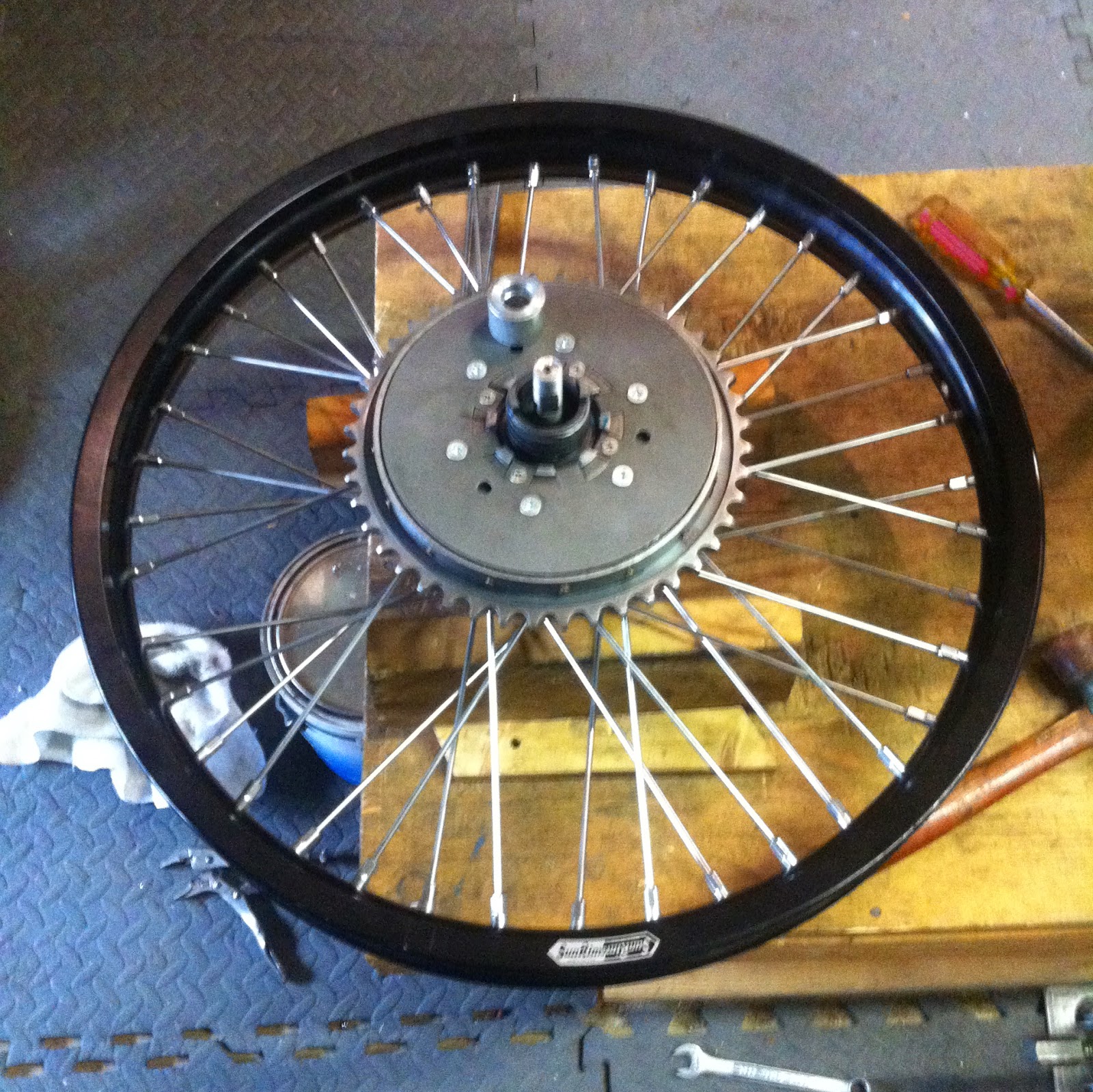
Lacing and truing spoked wheels is an acquired skill best left to professionals. I usually use Buchanan Spoke & Rim to build my spoked wheels. They did the original wheels on my racer, but that was not really an option in this case. I have only laced, and trued, a couple of wheels in my time, but that was many years ago. My first mistake was not photographing my original rear wheel before disassembling it for the spokes & rim. I laced, and re-laced, the rear wheel countless times, before I finally got it right. Pretty much, what I remembered of lacing the first spoked wheel 43 years ago!
Finished Rear Wheel Ready for Truing
The next step is truing the rim. This twostep process, and starts with horizontal truing, which allows the wheel to run true side to side.
Horizontal Wheel Truing
Once the wheel runs true horizontally, it's time to concentrate on vertical truing, which allows the wheel to run true, with no up and down hop.
Vertical Wheel Truing
After a couple of hours, everything was running true. Now comes another fun part. Mounting a modern tire to a 1.85" rim, without pinching the tube, is a real art. After about an hour of flying tire irons, and a more than few choice words, the rear tire was mounted, and held air.
Completed Freewheel Clutch Rear Wheel
With the rear wheel setup completed, my next task was to fabricate a clutch lever to activate the rear wheel clutch. I had previously ordered the rod that connects the clutch lever to the clutch, but the casting that mounts the clutch lever to the frame's seat support tube, is no longer available. After some trial, and error, I came up with a mount for the lever.
Clutch Lever in the Drive Position
Pushing the lever forward engages the clutch and drives the rear wheel. Pulling the lever back disengages the clutch, allowing the rear sprocket to spin on the rear hub, without driving the rear wheel. A quadrant gate on the lever mount, controls the available lever travel, and a spring-loaded tensioner holds the lever in place at either the drive, or non-drive setting. This video, shows the rear wheel clutch function with the engine running:
Live Engine Clutch Test Video
Now that all the fabrication was dome, and the rear wheel was mounted to the frame, it was time to determine how much the rear wheel was off from the frame's center line. This was done by checking the front and rear wheel alignment using a 6' long piece of angle iron as a straight edge.
Rear Wheel Alignment Check
The final verdict is the rear wheel is off center to the right around 3/8 of an inch. Really not as bad, as I first thought.
Front Wheel Shows a 3/8" Rear Wheel Misalignment to the Right
So, what lessons did I learn from this experience?
This has by far, been the most expensive motorcycle project, that I've ever built. Adding the clutch contributed significantly to the total cost and time involved in this project. I was also warned by people in the know, that the clutch supplier had problems, and that using his clutch would involve a lot of work. That was true, and knowing what I know now, I would probably not do it again. I've said before that building replicas of these old racers is not a job for amateur builders. This episode confirmed that. But in the long run, it will all be forgotten with the first blast down the road, and that's really what it's all about!